Start01 / 18
Print the set
Nine prints, all from the kit. 0.16 mm layers · 0.42 line · elephant-foot 0 · no supports anywhere. Carbon-fibre PETG for the structure, clear PETG for the ring, ASA for the posture base. The plate prints face up with ironing on; the sheets print pocket side up.
The chassis file holds three bodies — the chassis and two flush inlays (the emblem on the front flank, O.R.B. on the rear). Load it as one object with parts and paint the inlays for a two-colour mark. The face plate's marks sit on four levels, so a height-range paint colours each group in one fill.
The chassis file holds three bodies — the chassis and two flush inlays (the emblem on the front flank, O.R.B. on the rear). Load it as one object with parts and paint the inlays for a two-colour mark. The face plate's marks sit on four levels, so a height-range paint colours each group in one fill.
| material | on the bed | |
|---|---|---|
orb2_01_chassis | PETG-CF (3 bodies: chassis + 2 flush inlays) | desk face down |
orb2_02_cap-carrier | PETG-CF | flat, bottom down |
orb2_03_deck | PETG-CF | flat, bottom down |
orb2_04_axle-pins | PETG-CF (×4, one spare) | standing, brim on — or cut Ø3 steel to 8.6 |
orb2_05_scroll-ring | clear PETG | top face down on a smooth plate |
orb2_06_sheet-W | PETG-CF | flat, pocket side up |
orb2_07_sheet-E | PETG-CF | flat, pocket side up |
orb2_08_face-plate | PETG-CF (+ 8 clear plugs) | face UP, ironing on |
orb2_09_posture-base | ASA or PETG-CF | flat, bottom down |
Chassis02 / 18
Chassis: magnets, then read the floor
- Magnets. A pair of small discs into each pocket on top of the wall towers, all the same pole up; the plate's magnets must attract them. One tower carries the plate's locating pin.
- Read the floor. The battery bay sits between two end walls at the west end, with the touch board's carrier resting on them. The sensor bosses, the deck columns and the deck pins are in the centre. The two haptic drivers and the controller cradle are east. Along both walls, on bare floor, run the two wire channels — every label is engraved in the floor where you need it.
- magnet pockets + one pin on the towers
- battery bay west · haptic drivers east
- two wall channels
Wiring03 / 18
Bench: build the spine
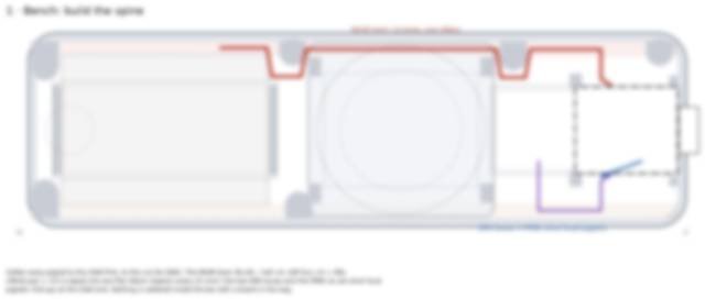
The controller is the hub. Both looms are soldered to it on the bench as one spine harness before anything goes into the bar. Every pigtail is cut to a list, each loom is taped into a flat ribbon, and the pull-ups and the LED series resistor sit at the controller end.
Rear loom power · the two hall sensors · the touch controller's bus and interrupt · the west actuator pair — thirteen wires, one ribbon.
Local pigtails the east haptic driver under the controller · the west haptic driver via the front channel · the optical sensor's six leads · the LED data line.
Rear loom power · the two hall sensors · the touch controller's bus and interrupt · the west actuator pair — thirteen wires, one ribbon.
Local pigtails the east haptic driver under the controller · the west haptic driver via the front channel · the optical sensor's six leads · the LED data line.
- thirteen wires, one ribbon
- pull-ups at the controller end
- every pigtail cut to a list
Cut list — every wire, from → to, quantity × length
Thirteen rear-loom wires, ten front-channel wires, the local pigtails and the LED hops — cut to length with the risers and slack included. The list is in the Build Edition.
Controller pin map
Every pin, every net, every board it goes to — one table. In the Build Edition.
Wiring04 / 18
Lay the spine in one move
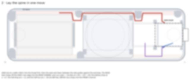
The controller drops into its cradle, USB-C into the wall throat first, then the west end down between the side guides against the end stop. The rear loom falls off its rear edge into the rear channel and runs west, tacked at three points; the drops for the battery, the halls and the touch board hang free where they'll be needed. The west haptic driver's bus drops into the front channel and waits.
Both channels are bare floor; at each closure tower the loom steps inboard and back.
Both channels are bare floor; at each closure tower the loom steps inboard and back.
- controller into the cradle, USB first
- rear loom into the rear channel
- west bus into the front channel
Wiring05 / 18
Floor boards join
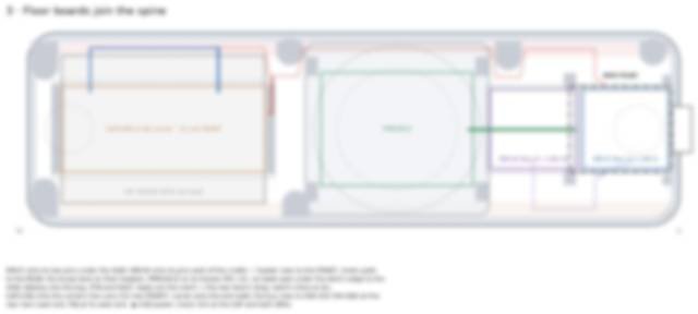
- Two haptic drivers onto their pins — one under the controller for the east actuator, one beside it for the west — header rows to the front, motor pads to the rear.
- The optical sensor board onto its four bosses, component side down, four screws from above, lens window over the ball centre. Its leads head east under the deck's edge.
- The battery into the west bay, circuit-board end east, leads out through the notch; the slide switch inline; it joins the rear loom's drop.
- The touch controller onto the carrier's four pins, sense row to the front; the carrier onto the two end walls — it is also the battery's lid. Its bus rises from the rear channel.
▶ USB power. Check the 3.3 V rail at the touch board and both drivers.
- drivers on pins: headers front, pads rear
- battery circuit-board end east
- touch board on the carrier, sense row front
Build Edition06 / 18
Twelve more steps
That was the chassis and the spine — the part of the build most guides skip. The Build Edition continues from here: the deck with its three caged bearings, the ring and its twelve magnets, the copper on the electrode sheets, the LED chain, the face plate with its two actuators, the posture base, the firmware and the Handshake — twelve more steps, every wire drawn, every diagram a click away, and the nine print files named in this order.
Get the Build Edition — $49 → What's in it
Get the Build Edition — $49 → What's in it
- nine prints, numbered
- 18 steps, animated
- BOM · cut list · pin map · template · firmware